
DS integrates TRUMPF / IPG fiber laser sources, high-precision industrial robots, laser processing heads, positioners, fixtures, and Robotmaster® offline programming to provide integrated solutions for 3D laser cutting and precision laser welding. Depending on material, workpiece geometry, thickness, cycle time, and quality requirements, the system can be configured with 2–6 kW laser sources and dedicated cutting or welding heads. Welding applications can also integrate wire feeders, visible-light alignment / vision modules, and custom fixtures to support autogenous welding, wire-fed welding, complex 3D paths, and multi-angle processing.
The LSC-2P / LSC-2TP / LSW-2P / LSW-2TP series combines TCP, Base, WOBJ, and Laser Tool calibration to improve coordinate consistency between offline models and the actual equipment. With Robotmaster®, machining paths can be generated from 3D CAD data with posture optimization, reachability analysis, collision checking, and program output, reducing on-site teaching and program adjustment time.
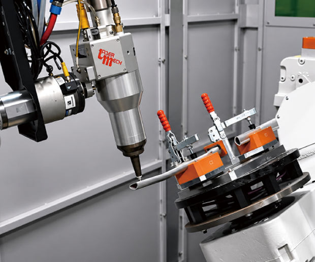
Robots are selected according to workpiece size, working range, payload, and accuracy requirements, with TCP, Base, WOBJ, and Laser Tool calibration performed accordingly.
Robotmaster® generates processing paths from 3D CAD data and supports posture optimization, reachability analysis, collision checking, and offline program output, reducing on-site teaching and adjustment while improving coordinate consistency between the virtual model and actual equipment.
Supports 3D workpieces, irregular tubes, complex surfaces, and multi-angle processing, including hole cutting, trimming, contour cutting, and 360° circumferential cutting.
Laser power, processing speed, focal position, and robot path are configured according to material, thickness, and workpiece geometry to establish a stable and repeatable 3D laser cutting process.
Integrates joint design, assembly gap control, fixture positioning, welding paths, and laser parameters, with optional wire feeders, visible-light alignment / vision modules, and positioners.
Process validation is used to establish stable penetration and fusion quality while reducing heat input, heat-affected zones, and welding distortion.
2P
Modular
A modular laser processing cell integrating an industrial robot, laser cutting head, positioner, fixtures, and Robotmaster® offline programming. It supports complex surfaces, irregular tubes, hole cutting, trimming, contour cutting, and multi-angle 3D laser cutting.
A modular laser welding cell integrating an industrial robot, laser welding head, positioner, fixtures, and Robotmaster® offline programming. It supports butt welding, lap welding, circumferential welding, complex surfaces, and 3D welding paths.
2TP
Rotary Dual-Station
A rotary dual-station laser cutting cell integrating an industrial robot, laser cutting head, dual-station rotary table, fixtures, and Robotmaster® offline programming. It supports complex contours, irregular tubes, multi-angle processing, and 360° circumferential cutting. The rotary table alternates between the processing and loading/unloading stations, allowing workpiece preparation while the other station is being processed to improve process continuity and equipment utilization.
A rotary dual-station laser welding cell integrating an industrial robot, laser welding head, dual-station rotary table, fixtures, and Robotmaster® offline programming. It supports butt welding, lap welding, circumferential welding, complex 3D paths, and multi-angle precision welding. The rotary table allows workpiece preparation at one station while welding is performed at the other, improving process continuity and equipment utilization.
Applicable to LSW Series
01
Supports laser welding processes requiring filler wire, with configurations based on filler material, wire diameter, and welding parameters.
02
Assists with weld-position verification, workpiece alignment, and path setup. Actual functions depend on the welding head, vision system, and project configuration.
03
Provides workpiece rotation, tilting, and multi-angle positioning for circumferential welding, curved-surface welding, and complex 3D welding paths.
04
Fixtures are designed according to workpiece geometry, joint design, and gap-control requirements to improve positioning consistency and welding process stability.
05
Generates robotic welding paths from 3D CAD data with posture optimization, reachability analysis, collision checking, and program output, reducing on-site teaching and program adjustment time.
Establishes consistent coordinate references among the robot, workpiece, and laser tool to reduce discrepancies between offline models and actual equipment.
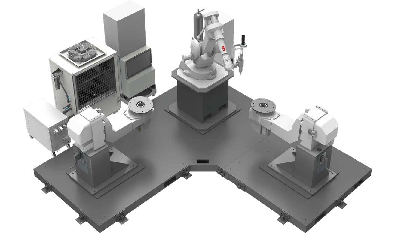
LSC-2P
01
TCP, Base, WOBJ, and Laser Tool calibration combined with on-machine validation reduces coordinate discrepancies between offline models and actual equipment, improving consistency of laser cutting and welding paths.
02
Supports complex surfaces, irregular tubes, multi-angle cutting, 360° circumferential cutting, and 3D welding paths, with process planning based on material, thickness, joint design, and workpiece geometry.
03
Manages laser power, processing speed, focal position, path, and related process parameters according to cutting or welding requirements, with process validation supporting stable and consistent quality.
04
Generates robotic processing paths from 3D CAD data with posture optimization, reachability analysis, collision checking, and program output, reducing on-site teaching and program adjustment time.
05
Equipment status, process parameters, process results, and quality data can be integrated into SmartCore AI™ based on project requirements for process monitoring, quality traceability, and further analysis.
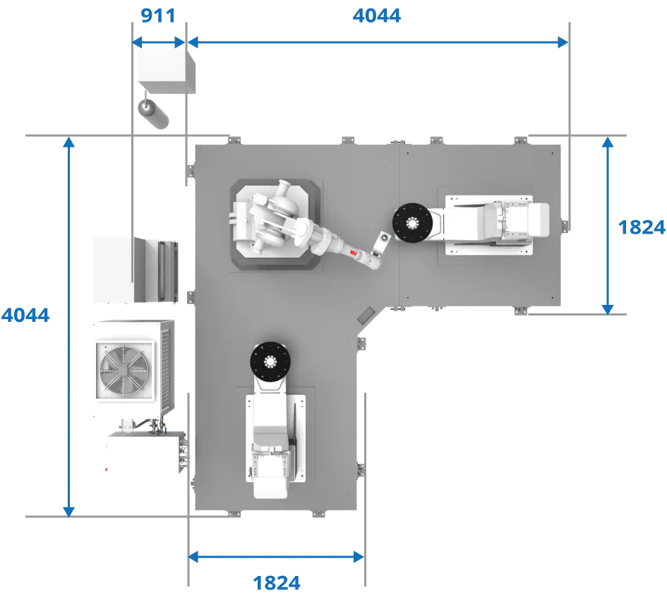
Reference configuration: approximately 4,044 x 4,044 mm. Actual dimensions and equipment layout are planned according to robot working range, laser source, processing head, workpiece size, positioner, safety requirements, and site conditions.
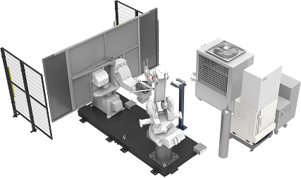
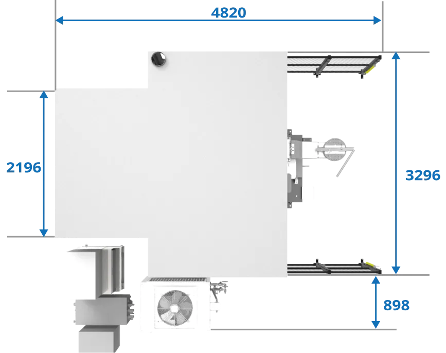
Reference configuration: approximately 4,820 x 3,296 mm. Actual system dimensions and equipment layout are planned according to the robot working range, laser source, laser processing head, dual-station rotary table, workpiece size, loading/unloading method, safety requirements, and site conditions.
Customized configurations are available for special workpieces, capacity requirements, loading/unloading methods, and site-specific conditions.
| Model | LSC Laser Cutting | LSW Laser Welding |
|---|---|---|
| System Overview | ||
| System Positioning | Robotic 3D Laser Cutting | Robotic Precision Laser Welding |
| System Configuration | LSC-2P/LSC-2TP | LSW-2P/LSW-2TP |
| Standard Module Size | 2P: approx. 4,044 x 4,044 mm; 2TP: approx. 4,820 x 3,296 mm | |
| Customized Configuration | Customized designs are available based on special workpieces, capacity, process requirements, loading/unloading methods, and site conditions. | Customized designs are available based on special workpieces, capacity, welding process requirements, loading/unloading methods, and site conditions. |
| Hardware Configuration | ||
| Laser Source | Standard 2–6 kW fiber laser configuration; other power levels can be evaluated based on project requirements. | |
| Laser Processing Head | Laser Cutting Head | Laser Welding Head |
| Robot Selection | Selected based on working range, load, and process requirements. | |
| Positioner | Configured based on workpiece geometry and process requirements | Configured based on workpiece geometry, joint type, and welding requirements |
| Wire Feeder | - | Optional, supports wire-fed laser welding |
| Visible-Light Alignment / Vision | Optional, based on project requirements | Optional, supports workpiece alignment, welding position confirmation, and path setting |
| Process Capabilities | ||
| Main Processes | Hole cutting, trimming, contour cutting, 360° circumferential cutting, complex surfaces, and multi-angle 3D cutting | Butt welding, lap welding, circumferential welding, complex surfaces, 3D welding paths, and multi-angle welding |
| Process Parameter Management | Recipe management based on material, thickness, laser power, processing speed, focal position, and process conditions | Recipe management based on material, thickness, joint design, laser power, welding speed, focal position, and wire-feeding conditions |
| Software and Data | ||
| High-Precision Calibration | TCP / Base / WOBJ / Laser Tool Calibration | |
| Offline Programming | Robotmaster® 3D CAD path generation, posture optimization, reachability analysis, collision checking, and program output | |
| SmartCore AI™ Integration | Optional | Integrates equipment status, cutting parameters, process results, and quality data | Integrates equipment status, welding parameters, process results, and quality data |
| Product Identification | Optional | QR Code/Barcode | |
01
Cutting thickness and processing speed are evaluated based on material type, thickness, laser power, processing head, assist gas, focal position, and quality requirements. A single fixed value should not be considered a guaranteed performance specification for all applications.
02
Actual processing accuracy depends on robot performance, TCP / coordinate calibration, workpiece geometry, fixtures, processing paths, and process conditions. It can be verified through actual sample testing and 3D Scan-to-CAD analysis according to project requirements.
03
Processing parameters for different products, materials, and process conditions can be stored and managed. Corresponding Recipes and processing paths can be recalled through product identification to support changeovers and process error-proofing.
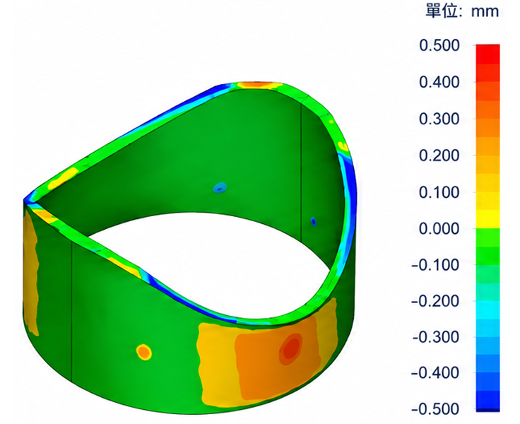
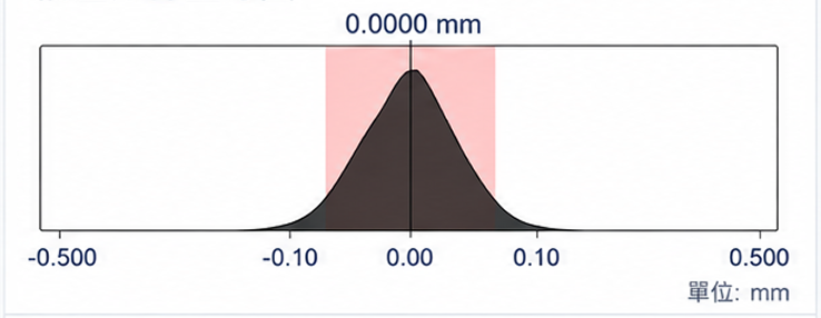
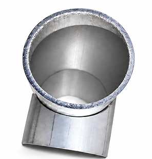
By comparing the physical workpiece with the original CAD model using 3D scanning, contour deviation, mean deviation, and standard deviation can be quantified while local abnormal areas are identified. The results provide a basis for optimizing robot paths, TCP / coordinate calibration, fixture positioning, and laser processing parameters. In this case, the statistical results show an average deviation of approximately 0.003 mm and a standard deviation of approximately 0.127 mm.
3D Deviation Map
Deviation Distribution Histogram
Physical Sample
Statistical Summary
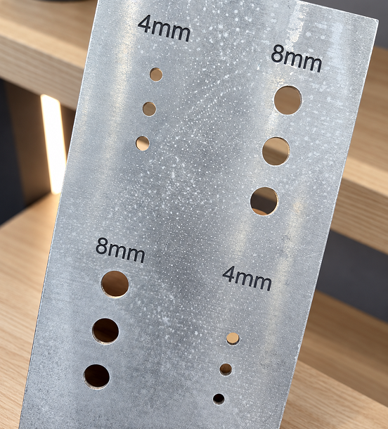
Φ4 mm and Φ8 mm small-hole laser cutting is used to verify robot trajectory stability on small-radius, high-curvature paths, as well as TCP / coordinate calibration consistency, hole-position repeatability, and diameter consistency. This type of machining is highly sensitive to robot path control and provides an effective method for evaluating path accuracy, repeatability, and coordinate consistency in robotic laser processing systems.
For small holes and circular contours, hole position, diameter, circularity, and edge quality are evaluated, together with the effects of robot path, TCP calibration, and processing-speed variations on cutting results.
The same path-control capability can be extended to small-diameter circumferential welding, circular weld seams, and complex curved welding paths to evaluate trajectory tracking, focal-position stability, welding-speed control, and start/end seam consistency.
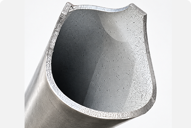
Supports continuous 360° cutting of aluminum irregular tubes and complex surfaces, demonstrating robotic 3D laser cutting capability in complex-path control and consistent edge quality.
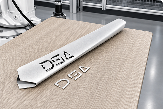
Supports lettering, hole cutting, and contour cutting on aluminum tubular parts according to product requirements, suitable for customized appearance, functional openings, and diversified product designs.
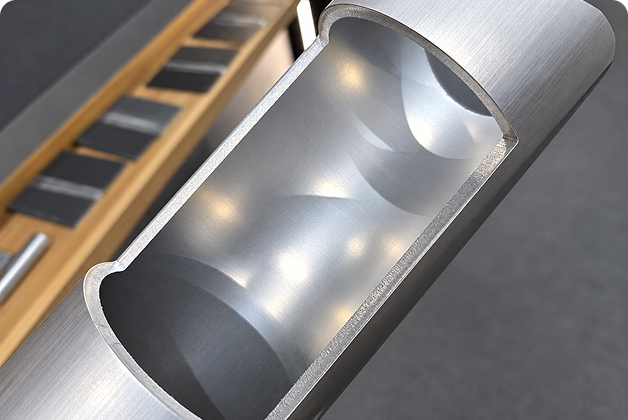
Performs opening cuts on 4 mm thick aluminum tubes to evaluate edge quality, contour integrity, and process consistency, demonstrating laser cutting capability for thicker-wall tubular components.
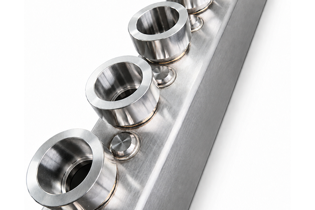
Precision laser welding for stainless-steel liquid-cooling tubes and joints, supporting consistent weld seams, assembly accuracy, and joint quality for high-reliability fluid-component manufacturing.
2–6 kW fiber laser sources can be configured according to material, thickness, and processing requirements. In general, higher laser power increases thick-material capability and available cutting speed, while cutting speed typically decreases as material thickness increases. Actual processing capability is still affected by material properties, workpiece geometry, laser source, cutting head, assist gas, focal position, workpiece orientation, and quality requirements.
| Laser Power | Carbon Steel / Structural Steel | Stainless Steel | Aluminum Alloy | Copper | Brass |
|---|---|---|---|---|---|
| 2 kW | Approx. 15–16 mm | Approx. 8 mm | Approx. 5 mm | Approx. 2.5 mm | Approx. 2.5 mm |
| 3 kW | Approx. 20 mm | Approx. 15–16 mm | Approx. 15–16 mm | Approx. 5–6 mm | Approx. 5–6 mm |
| 4 kW | Approx. 20–25 mm | Approx. 20 mm | Approx. 15–20 mm | Approx. 8 mm | Approx. 8 mm |
| 5 kW | Subject to equipment & process evaluation | ||||
| 6 kW | Approx. 20–25 mm | Approx. 20–25 mm | Approx. 20–25 mm | Approx. 10 mm | Approx. 10 mm |
Note: The above values are reference values for laser equipment and processes, not fixed performance guarantees of the DS system; actual cutting thickness and speed must be verified according to material, workpiece geometry, laser parameters, processing head, fixtures, and quality requirements.
Laser welding performance is primarily affected by laser power, welding speed, focal position, material properties, joint design, assembly gap, and whether filler wire is used. In general, when other conditions are similar, increasing laser power can increase achievable penetration or welding speed, while increasing welding speed typically reduces heat input per unit length and penetration depth.
| Laser Power | Typical Aluminum Penetration | Typical Stainless-Steel Penetration | Typical Mild-Steel Penetration |
|---|---|---|---|
| 2 kW | Approx. 2 mm | Approx. 3 mm | Approx. 3 mm |
| 3 kW | Approx. 3 mm | Approx. 5 mm | Approx. 5 mm |
| 4 kW | Approx. 4 mm | Approx. 7 mm | Approx. 7 mm |
| 5 kW | Approx. 5 mm | Approx. 8 mm | Approx. 8 mm |
| 6 kW | Approx. 6 mm | Approx. 10 mm | Approx. 10 mm |
The following values are reference data for laser equipment and processes. Actual processing capability must be validated according to project-specific conditions.
| Material & Thickness | 2 mm Aluminum Alloy | 1.5 mm Stainless Steel | 3 mm Mild Steel |
|---|---|---|---|
| 3 kW | Approx. 7 m/min | Approx. 8 m/min | Approx. 3 m/min |
| 6 kW | Approx. 10.2 m/min | Approx. 13 m/min | Approx. 7 m/min |
Note: The above values are reference data for laser equipment and processes; actual welding penetration and speed must be verified according to material, workpiece geometry, laser source, welding head, focal position, joint design, whether filler wire is used, fixtures, and quality requirements.
Laser cutting and laser welding are continuous-path processes. The key performance factors are not limited to point positioning accuracy, but also include path accuracy, path repeatability, and speed stability along the complete 3D trajectory. Actual robot path performance varies with robot model, payload, speed, posture, and process conditions. DS applies TCP, Base, WOBJ, and Laser Tool calibration together with Robotmaster® offline programming and on-machine validation to reduce deviations between virtual paths and actual robot trajectories, improving consistency in laser cutting contours and welding paths.
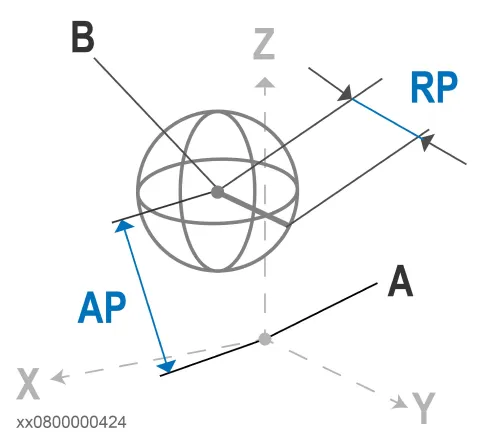
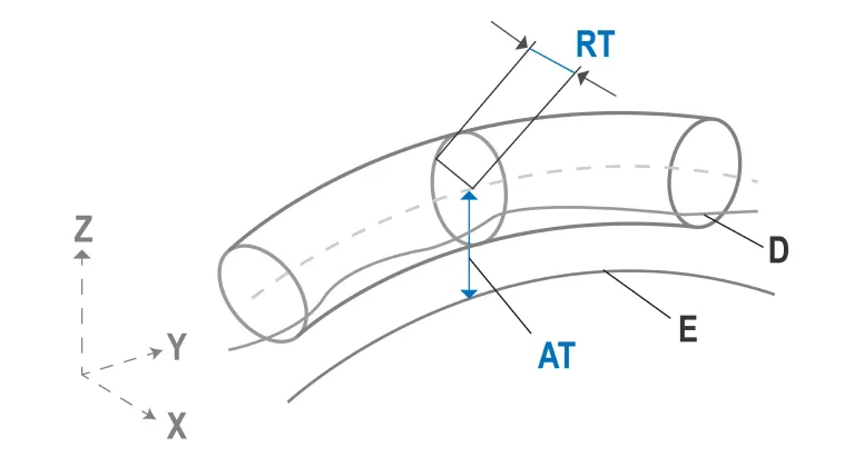
| Item | IRB 2400/10 | IRB 2400/16 | IRB 4400/60 | IRB 4400/L10 |
|---|---|---|---|---|
| Pose Repeatability, RP (mm) | 0.03 | 0.03 | 0.06 | 0.05 |
| Pose Accuracy, AP (mm) | 0.03 | 0.03 | 0.03 | 0.04 |
| Linear Path Repeatability, RT (mm) | 0.11 | 0.15 | 0.09 | 0.16 |
| Linear Path Accuracy, AT (mm) | 0.33 | 0.41 | 0.36 | 0.34 |
| Pose Stabilization Time, PSt (s) | 0.15 | 0.22 | 0.27 | 0.25 |
Note: The above values are ABB robot reference specifications. Actual laser processing accuracy is also affected by TCP / coordinate calibration, workpiece geometry, robot posture, speed, fixtures, laser processing head, and process conditions, and should not be interpreted as guaranteed DS system accuracy.
For robotic laser processing, Path Accuracy and Path Repeatability are more relevant than point-based Position Accuracy and Repeatability, because cutting and welding quality depends on the robot’s actual motion throughout the entire continuous trajectory, not only its ability to reach individual points accurately.
DS provides end-to-end services from laser process evaluation, parameter validation, fixture and system design to robotic automation integration and production ramp-up. LSC / LSW systems are available in standard modular or customized configurations based on cutting / welding processes, workpieces, production capacity, and site conditions.